PyCirc - Python Logic Circuit Modeling
and Simulation Package
- Link to GITHUB repository
Link to the the Google Colaboratory notebook
- The Google Colaboratory notebook has the advantage that you can run PyCirc from it without having to install PyCirc or even Python on your local system.
- You first need to copy it to your google drive (or github repository)
- You can also dowload it to your local device and open it as a Jupyter notebook (if you have it installed with your Python).
Installing the PyCirc package
- The PyCirc package can be installed on your local system by running the following command from the command line
pip install pycirc - Or you may try running one of the following commands from this notebook.
- If you are running it from a Jupyter notebook on your local system, then it will be installed on your device.
# To install from this notebook, uncomment the next line and run this cell.
# %pip install pycirc==1.32
# This should also work:
# !pip install --upgrade pycirc

# After installation, you have to restart this notebook.
# Make sure to comment the %pip or !pip lines above to avoid reinstall each time you run this notebook.

# To uninstall the package use:
# %pip uninstall pycirc
# or
# !pip uninstall pycirc
- After installation, you may need to restart this notebook.
Loading the PyCirc package
- After installing the PyCirc package, you need to import it.
- The following command imports PyCirc to your Python interpreter.
from pycirc import *
Loading builtin box cells..
Introduction
- PyCirc is a new Python package for modeling and simulating simple Logic Circuits specifically designed for educational use in introductory computation and digital logic college course.
- As such, it was primarily tuned for simplicity, readability
convenience, and fast learning curve.
- Less for speed or industrial production.
- It is a light weight package especially designed for small to medium scale circuits, such as those that are studied in introductory academic courses on the theory of computation and electronic digital design.
- Its main characteristic is that a digital circuit can be easily defined by a series of simple Python commands, rather than an external static language.
- So, the only requirement is a basic knowledge of the Python programming language, with a little programming skill.
- Experienced Python programmers can probably benefit a lot more from this package.
- It can be a useful companion for theoretical courses on
computation models and languages who wish also to engage
the students with some programming experience and skills.
- It is planned to be used in such a course by the author (Hebrew book at http://samyzaf.com/afl.pdf).
- It enables students to easily model and experiment with
- Typical logic circuit design
- Logic Circuit Modeling and Validation
- Logic Circuit Testing
- Logic problem solving
- It does provide an opportunity for students to develop and practice some programming skills while covering the theoretical computation course.
- In this tutorial, we will cover:
- Basic usage of PyCirc for modeling and manipulating Logic Circuits.
- A short survey of the commands and tools of the PyCirc package.
- Examples for modeling Logic Circuits and their manipulation.
- Advanced usage of PyCirc for experienced Python programmers (TODO).
Example 1: The Circuit FOO
We start with a very simple logic circuit which we call "FOO"
- Inputs gates: $x_1$, $x_2$, $x_3$
- Output gates: $y_1$, $y_2$
- Logic action: $(y_1, y_2) = (x_1 \land x_2 , \ \neg x_3)$
This circuit can be represented by the following PyCirc Diagram
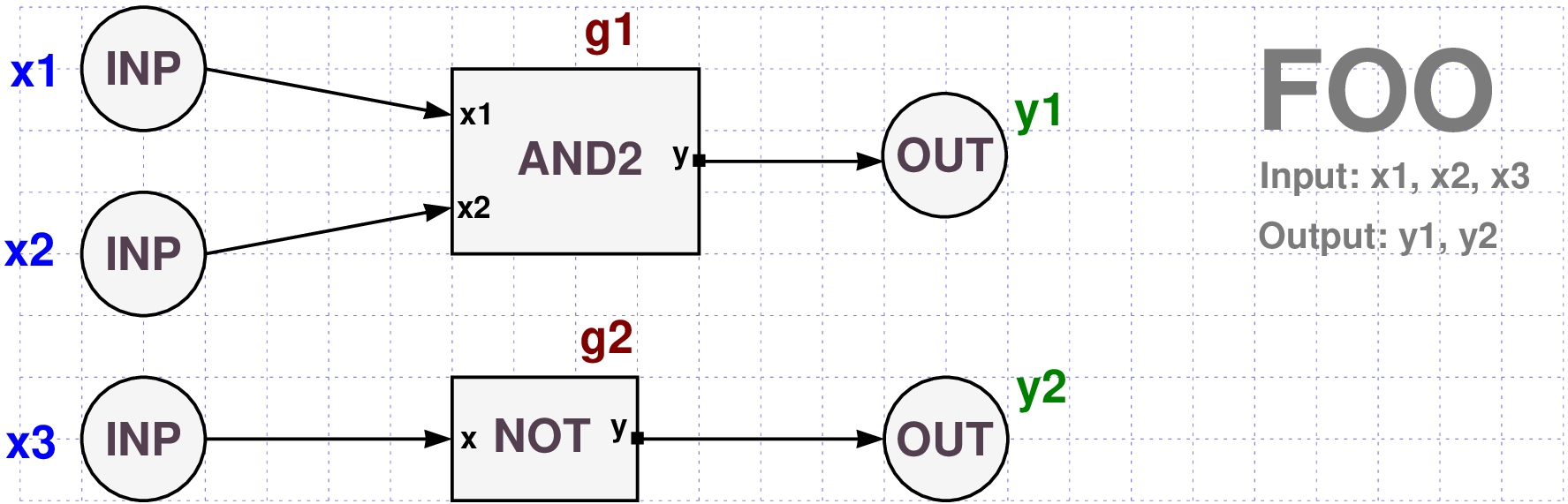
A PyCirc diagram is a simplified form of circuit diagram in which gates are represented by text blocks rather than special shape symbols.
- Many students find the usual gate symbols intimidating and hard to memorize.
- Plain text on a circle or a rectangle seems to be more convenient, especially for computation theory courses in which most of the participants do not have any electronics background (or plan to go in this direction).
- Input and output gates are represented by circles with an INP/OUT labels.
- The other logic gates are represented by rectangular blocks with input/output pins near the block edges.
- Input gate names are blue colored.
- Output gate names are green colored.
- Logic gate names are brown colored.
- Connections ("Wires") are represented by arrowed lines from source pin to target pin.
- A pin is either an input/output gate or a named entry/exit point to a logic gate.
- In the above diagram we have 5 wires and 10 pins:
- 3 Input gates: x1, x2, x3
- 2 output gates: y1, y2
- 5 Block pins: g1/x1, g1/x2, g1/y, g2/x, g2/y
- Note the special notation g/p for the block pins.
- g stands for the gate name and p is the input/ouput name of the cell type of the gate.
- Here is the PyCirc code for modeling this circuit:
Define("foo")
GATE (name="x1", type="inp")
GATE (name="x2", type="inp")
GATE (name="x3", type="inp")
GATE (name="y1", type="out")
GATE (name="y2", type="out")
GATE (name="g1", type="and2")
GATE (name="g2", type="not")

WIRE ("x1",   "g1/x1")
WIRE ("x2",   "g1/x2")
WIRE ("x3",   "g2/x")
WIRE ("g1/y", "y1")
WIRE ("g2/y", "y2")
EndDef()
Cell = foo: Validity check: OK.
<pycirc.pycirc.PyCirc at 0x7f7719d59990>
Notic that this is a pure Python code!
- So you need to run its cell in order to execute it.
A definition starts with the
Define()function call which accepts the cell name as its first argument.- The definition ends with the
EndDef()function call. - A cell definition consists of
GATEandWIREfunction calls.- The
GATEfunction call accepts the name and the logic type of the gate. - The
WIREfunction call connects a source pin to a target pin.
- The
- A pin notation
g/pconsists of a gate namegand a pin namep.- The pin
pis either an input or an output pin of the gate cell.
- The pin
- For example the expression
"g1/x2"designates the input pin"x2"of the gate"g1". - The flag "name=" is optional.
It is enough to specify the name only:
GATE("x1", type="inp")
- The 'type' flag indicates the logic cell name to which the gate is an instance of.
- Input gates are the circuit elements in which we feed the input (boolean values).
- Output gate are the circuit elements from which we read the output after its computation is done.
- All remaining gates are called logical gates.
- They usually have incoming wires and outgoing wires and they perform some logic action.
- We repeat: the above definition of the cell FOO is also a pure Python code!
- This means that you can include it inside longer Python
programs/scripts and manipulate cells dynamically.
- For example, it is possible to add or remove gates or wires in a circuit dynamically and run it for optimization goals.
Cell libraries
- After successful design of a circuit such as FOO,
it can be placed as a single file 'foo.py' in
a cell library and loaded by the load command
load("foo")
- A cell library is simply a directory that contains cell files.
- You may have several directories, including directories residng on far Internet locations.
- You specify the library with a list such as
set_libpath(["c:/eda/pycirc/lib", "d:/cmfl/code/logcirc/lib", "https://samyzaf.com/pycirc/lib"])
We will use this library path in this notebook, but you can download all cell files from the following url and place them on your local computer, and change the libpath accordingly.
In most cases it is better to use the need command
need("foo")
which loads the cell only if it was not already loaded.
# You need to edit this list.
# Replace the first two library paths to ones in your local system.
# Or just leave the last one to load cells from pycirc web site.

set_path(["c:/eda/pycirc/lib", "d:/cmfl/code/logcirc/lib1", "https://samyzaf.com/pycirc/lib"])
- You may want to copy the library of cells we use in this notebook to your local pc.
- Here is a link to a zip file that contains all the cells we use here:
- You can also browse this library and pick individual files from it
- After copying it to your local space, you can add more cells to it, or create more libraries like it.
- If you do, don't forget to update the new list with the set_libpath command:
set_libpath([ dir1, dir2, url1, url2, ...])
Gates as Cell Instances
- Once we have defined a cell such as FOO, we can use it as a building block element inside the definitions of new cells.
- Every logic gate in a logic circuit must be an instance of some cell.
- Typically, there can be several instances of the same cell in a logic circuit definition.
- This is how the FOO cell is represented as a single block element in a logic circuit
- It appears as a named black box with only entry and exit points (pins)

The Circuit FRED
- Here is an example of cell called FRED which uses an instance of the cell FOO as one of its building blocks.
# CELL: FRED
# This cell is using a gate of type FOO which we defined earlier
# so we issue a need command:
need("foo")

Define("fred")
GATE("x1", type="inp")            # No need to use: name="x1"
GATE("x2", type="inp")
GATE("y1", type="out")
GATE("y2", type="out")
GATE("g1", type="foo")            # Here we define a gate g1 of type FOO !   <<<<<<<
GATE("g0", type="zero")

WIRE("x1", "g1/x1")
WIRE("x2", "g1/x2")
WIRE("g0", "g1/x3")
WIRE("g1/y1", "y1")
WIRE("g1/y2", "y2")
EndDef()
Cell = fred: Validity check: OK.
<pycirc.pycirc.PyCirc at 0x7f77193bab90>
- The first line of code is
need("foo")which loads the definition of the cell FOO from our cell library, if it was not already loaded. - Usually every cell is defined in a single file "cell.py", but several cells can also be defined in one file.
- You create a library by
- allocating a folder or a url for it.
- putting all your cell definitions in this folder.
- adding this directory (or url) to the set_libpath list (see above).
- Note the line
GATE("g1", type="foo")in which the gate of type FOO is declared! It is easy to draw a PyCirc Diagram from the above definition
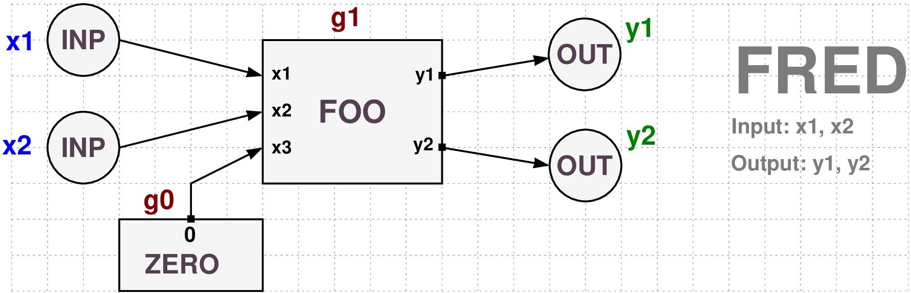
Note that we used the ZERO cell which has no inputs, and only one constant 0 output.
- It is the hardware equivalent of a boolean constant.
- We use it to fix the input x3 of gate g1 to zero.
- The ZERO cell is a fundamental PyCirc cell which is automatically loaded when PyCirc starts.
The Circuit HAM
- The follwing cell HAM contains two gates of type FOO and two gates of type XOR3.
- The XOR3 cell is a typical xor cell with 3 input gates (built in PyCirc).
- It also contains one gate of type NOT.
The XOR3 and NOT cells are built in types of PyCirc and are loaded automatically when PyCirc starts.
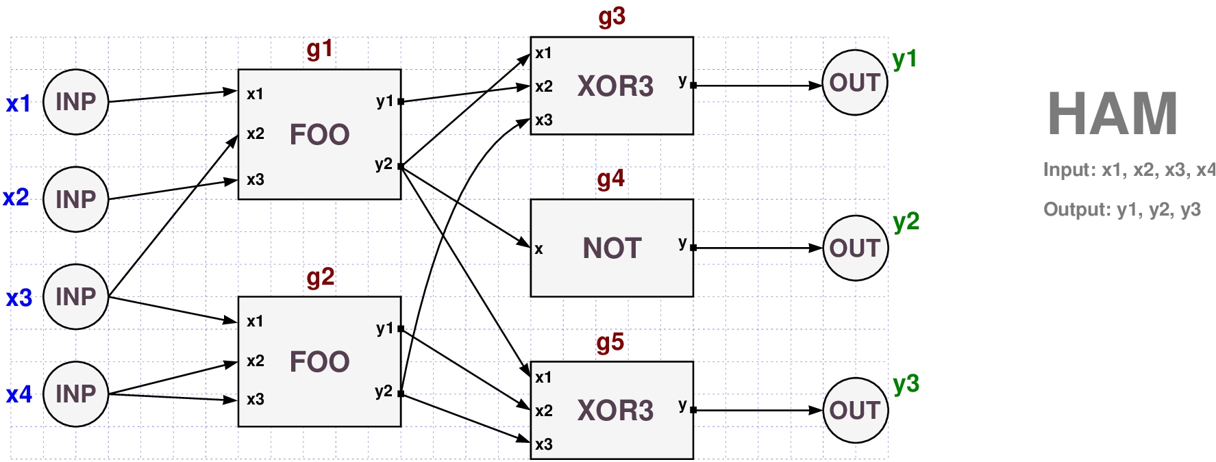
- Here is a PyCirc code for modeling this cell.
- Note the compressed notation style for writing shorter code.
# CELL: HAM
# This cell is using the FOO cell which we defined earlier
# so we issue a need command first:
need("foo")
# "xor3" is a basic cell in PyCirc - it is built in and loaded at start time.

Define("ham")
GATE("x<1:4>", type="inp")               # Input gates: x1, x2, x3, x4
GATE("y<1:3>", type="out")               # Output gates: y1, y2, y3
GATE("g1; g2", type="foo")               # Here we define two gates g1 and g2 of type FOO !
GATE("g4", type="not")
GATE("g3; g5", type="xor3")              # Here we define two gates g3 and g5 of type XOR3 !

WIRE("x1", "g1/x1")
WIRE("x2", "g1/x3")
WIRE("x3", "g1/x2; g2/x1")               # Two wires defined in one line:  "x3" -> "g1/x2"  and  "x3" -> "g2/x1"
WIRE("x4", "g2/x2; g2/x3")
WIRE("g1/y1", "g3/x2")
WIRE("g1/y2", "g3/x1; g4/x; g5/x1")      # Three wires defined in one line!
WIRE("g2/y1", "g5/x2")
WIRE("g2/y2", "g3/x3; g5/x3")
WIRE("g3/y", "y1")
WIRE("g4/y", "y2")
WIRE("g5/y", "y3")
EndDef()
Cell = ham: Validity check: OK.
<pycirc.pycirc.PyCirc at 0x7f7713b57f90>
- Note that
"x<1:4>"stands forx1, x2, x3, x4 - Instead of writing 4 lines of codeWe can write one equivalent line!
GATE("x1", type="inp")
GATE("x2", type="inp")
GATE("x3", type="inp")
GATE("x4", type="inp")
GATE("x<1:4>", type="inp")
- Instead of writingWe can simply write
WIRE("g1/y2", "g3/x1")
WIRE("g1/y2", "g4/x")
WIRE("g1/y2", "g5/x1")
WIRE("g1/y2", "g3/x1; g4/x; g5/x1")
- Arguments can also be lists or tuples of compressed names!
WIRE("g1/y2", ["g%s/x%s" % (i,) for i in range(20)])
- More on compressed notation in the examples below.
- The only supported modes:
- one to one
- one to many
- many to one
- n to n
Cell Query and Manipulation
- After defining the cell HAM we may start performing all kind of queries on it.
- First we need to get a reference to it.
# Get a reference to HAM

ham = PyCirc["ham"]
- This gives us a reference to our
hamcircuit object. which we can use to manipulate the cell. PyCircis the name of the Python class which creates logic circuit objects.- The class
PyCirckeeps a map between the name and the reference of every logic circuit created by it. - So if you have the name of an existing logic circuit, you can get a handle for it by
usinganywhere in your code.
ref = PyCirc[name]
- You may use
refas any other Python object handle for querying and manipulating the cell object.
# Print the gates in the circuit HAM

for g in ham.gates:
    print(g)
gate id=13: name=x1, type=inp, value=(None), depth=0
gate id=14: name=x2, type=inp, value=(None), depth=0
gate id=15: name=x3, type=inp, value=(None), depth=0
gate id=16: name=x4, type=inp, value=(None), depth=0
gate id=17: name=y1, type=out, value=(None), depth=3
gate id=18: name=y2, type=out, value=(None), depth=3
gate id=19: name=y3, type=out, value=(None), depth=3
gate id=20: name=g1, type=foo, value=(y1=None, y2=None), depth=1
gate id=21: name=g2, type=foo, value=(y1=None, y2=None), depth=1
gate id=22: name=g4, type=not, value=(y=None), depth=2
gate id=23: name=g3, type=xor3, value=(y=None), depth=2
gate id=24: name=g5, type=xor3, value=(y=None), depth=2
# Count the number of gates in the circuit HAM

print(len(ham.gates))
12
# Get names of input gates

for x in ham.input:
    print(x.name)
x1
x2
x3
x4
# Get names of output  gates

for x in ham.output:
    print(x.name)
y1
y2
y3
# Count the number of wires in the circuit HAM
print(len(ham.wires))
16
# List all XOR3 gates

for g in ham.gates:
    if g.type == "xor3":
        print(g)
gate id=23: name=g3, type=xor3, value=(y=None), depth=2
gate id=24: name=g5, type=xor3, value=(y=None), depth=2
# Get a reference to gate "g1"
g1 = ham["g1"]

# Print all outcoming gates from g1
for g in ham.out_gates(g1):
    print(g)
gate id=22: name=g4, type=not, value=(y=None), depth=2
gate id=23: name=g3, type=xor3, value=(y=None), depth=2
gate id=24: name=g5, type=xor3, value=(y=None), depth=2
- This gives us only gates and ignores pins.
- To get pin connections we need to dig a bit deeper.
# Print all outgoing wires from g1
for w in ham.out_wires(g1):
    print(w)
wire id=16:
  source=gate id=20: name=g1, type=foo, value=(y1=None, y2=None), depth=1
  target=gate id=23: name=g3, type=xor3, value=(y=None), depth=2
  source=y1
  target=x2
wire id=17:
  source=gate id=20: name=g1, type=foo, value=(y1=None, y2=None), depth=1
  target=gate id=23: name=g3, type=xor3, value=(y=None), depth=2
  source=y2
  target=x1
wire id=18:
  source=gate id=20: name=g1, type=foo, value=(y1=None, y2=None), depth=1
  target=gate id=22: name=g4, type=not, value=(y=None), depth=2
  source=y2
  target=x
wire id=19:
  source=gate id=20: name=g1, type=foo, value=(y1=None, y2=None), depth=1
  target=gate id=24: name=g5, type=xor3, value=(y=None), depth=2
  source=y2
  target=x1
- This is too verbose.
- We want to get a cleaner list of pin connections:
for w in ham.out_wires(g1):
    print("%s  =>  %s" % (w.source, w.target))
g1/y1  =>  g3/x2
g1/y2  =>  g3/x1
g1/y2  =>  g4/x
g1/y2  =>  g5/x1
# Get a reference to gate "g3"
g3 = ham["g3"]

# Print all incoming wires to gate g3
for w in ham.in_wires(g3):
    print("%s ==> %s" % (w.source, w.target))
g1/y1 ==> g3/x2
g1/y2 ==> g3/x1
g2/y2 ==> g3/x3
- Note the
ham["g3"]expression in the first line. - The cell object
hamhas been overloaded as a dictionary which maps gate and wire names to their reference. The following diagram displays examples of typical cell representations in the PyCirc package.

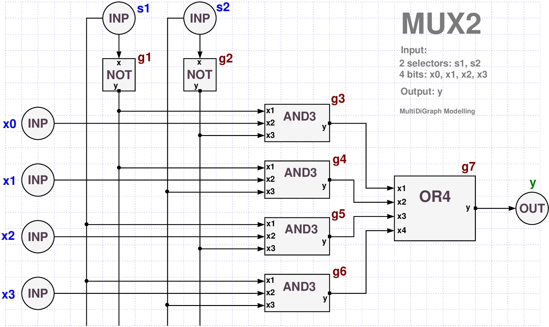
4x1 Multiplexer Design
- Multiplxers are important circuit elements in electronic design.
Here is a simple PyCirc Design Diagram and code for a 4x1 Multiplexer circuit (aka MUX2)
# MUX2
# input:  x3, x2, x1, x0, s2, s1
# output: y

Define("mux2")
GATE("x0", type="inp")
GATE("x1", type="inp")
GATE("x2", type="inp")
GATE("x3", type="inp")
GATE("s1", type="inp")
GATE("s2", type="inp")
GATE("y", type="out")
GATE("g1", type="not")
GATE("g2", type="not")
GATE("g3", type="and3")
GATE("g4", type="and3")
GATE("g5", type="and3")
GATE("g6", type="and3")
GATE("g7", type="or4")

WIRE("s1", "g1/x")
WIRE("s1", "g5/x1")
WIRE("s1", "g6/x1")
WIRE("s2", "g2/x")
WIRE("s2", "g4/x3")
WIRE("s2", "g6/x3")
WIRE("x0", "g3/x2")
WIRE("x1", "g4/x2")
WIRE("x2", "g5/x2")
WIRE("x3", "g6/x2")
WIRE("g1/y", "g3/x1")
WIRE("g1/y", "g4/x1")
WIRE("g2/y", "g3/x3")
WIRE("g2/y", "g5/x3")
WIRE("g3/y", "g7/x1")
WIRE("g4/y", "g7/x2")
WIRE("g5/y", "g7/x3")
WIRE("g6/y", "g7/x4")
WIRE("g7/y", "y")
EndDef()
Cell = mux2: Validity check: OK.
<pycirc.pycirc.PyCirc at 0x7f7713b83dd0>
- This is long. Took 35 lines of code to define this cell.
- With compressed notation it takes 15 lines!
- In addition, compressed notation can help us understand better the circuit structure, as it is displayed in one paragraph.
- Remember that this is a clean Python code, so you can use Python comments, and other Python commands.
# MUX2  (4x1 Multiplexer)
# input:  x3, x2, x1, x0, s2, s1
# output: y

Define("mux2")
GATE("x<0:3>", type="inp")             # 4 bits
GATE("s1;s2", type="inp")              # 2 selectors
GATE("y", type="out")
GATE("g1; g2", type="not")
GATE("g<3:6>", type="and3")            # 4 gates of basic type "and3"
GATE("g7", type="or4")

WIRE("s1", "g1/x; g5/x1; g6/x1")
WIRE("s2", "g2/x; g4/x3; g6/x3")       # 3 wires!
WIRE("x<0:3>", "g<3:6>/x2")
WIRE("g1/y", "g3/x1; g4/x1")
WIRE("g2/y", "g3/x3; g5/x3")
WIRE("g<3:6>/y", "g7/x<1:4>")          # 4 wires
WIRE("g7/y", "y")
EndDef()
Cell = mux2: Validity check: OK.
<pycirc.pycirc.PyCirc at 0x7f7713b7ffd0>
# get a grip on our MUX2 object

mux2 = PyCirc["mux2"]
- Lets print the list of gates in our circuit mux2:
for g in mux2.gates:
    print(g)
gate id=39: name=x0, type=inp, value=(None), depth=0
gate id=40: name=x1, type=inp, value=(None), depth=0
gate id=41: name=x2, type=inp, value=(None), depth=0
gate id=42: name=x3, type=inp, value=(None), depth=0
gate id=43: name=s1, type=inp, value=(None), depth=0
gate id=44: name=s2, type=inp, value=(None), depth=0
gate id=45: name=y, type=out, value=(None), depth=4
gate id=46: name=g1, type=not, value=(y=None), depth=1
gate id=47: name=g2, type=not, value=(y=None), depth=1
gate id=48: name=g3, type=and3, value=(y=None), depth=2
gate id=49: name=g4, type=and3, value=(y=None), depth=2
gate id=50: name=g5, type=and3, value=(y=None), depth=2
gate id=51: name=g6, type=and3, value=(y=None), depth=1
gate id=52: name=g7, type=or4, value=(y=None), depth=3
- This is too verbose, but useful for debugging purposes.
- To get more specific info, you may use code like this:
print("Gates list")
for g in mux2.gates:
    print("name = %s,   type = %s" % (g.name, g.type))
Gates list
name = x0,   type = inp
name = x1,   type = inp
name = x2,   type = inp
name = x3,   type = inp
name = s1,   type = inp
name = s2,   type = inp
name = y,   type = out
name = g1,   type = not
name = g2,   type = not
name = g3,   type = and3
name = g4,   type = and3
name = g5,   type = and3
name = g6,   type = and3
name = g7,   type = or4
Truth Assignments in PyCirc
- Truth assignment for a boolean formula or a boolean circuit is a mapping between its boolean variables and the two boolean values $\{0,1\}$.
- In PyCirc, trurth assignment is modeled by a Python class called Assign, which is a subclass of the standard Python dictionary class dict.
- An Assign object maps a list of gate names to one of three values:
{0, 1, None}. - The value
Noneindicates uninitialized state. - Here is a simple example for defining an assignment on four input variables.
a = Assign(["x1", "x2", "x3", "x4"], [0,0,1,1])
Here are some code examples for manipulating an Assign object
print(a)
x1=0, x2=0, x3=1, x4=1
for x in a.names:
    print(x)
x1
x2
x3
x4
a.bits()
'0011'
a.bits("x<1:3>")
'001'
a.bits(["x2", "x4"])
'01'
- An assignment object
ais callable (i.e., can be called as a function) - The result of the call
a()is the list of its bit values.
a()
[0, 0, 1, 1]
- You can pass bit names in expanded or compressed form:
a(["x2","x3"])
[0, 1]
a("x<2:4>")
[0, 1, 1]
- It is also possible to create an Assign object from keyword/value pairs, just like in a Python dictionary.
a = Assign.fromKeys(x1=0, x2=0, x3=1, x4=1)
print(a)
x1=0, x2=0, x3=1, x4=1
- The Assign class also accepts names in compressed form.
- The default of the second argument is
Nonefor all bits.
a = Assign("x<1:4>")
print(a)
x1=None, x2=None, x3=None, x4=None
- The
Nonevalue indicates that the input is uninitialized. - Use the following to initialize all values to zero (or one).
a = Assign("x<1:4>", 0)
print(a)
x1=0, x2=0, x3=0, x4=0
- The Assign class also has a static method Assign.iter for creating an iterator for looping over all truth assignments!
gates = ['x1', 'x2', 's1', 's2']
for a in Assign.iter(gates):
    print(a)
x1=0, x2=0, s1=0, s2=0
x1=0, x2=0, s1=0, s2=1
x1=0, x2=0, s1=1, s2=0
x1=0, x2=0, s1=1, s2=1
x1=0, x2=1, s1=0, s2=0
x1=0, x2=1, s1=0, s2=1
x1=0, x2=1, s1=1, s2=0
x1=0, x2=1, s1=1, s2=1
x1=1, x2=0, s1=0, s2=0
x1=1, x2=0, s1=0, s2=1
x1=1, x2=0, s1=1, s2=0
x1=1, x2=0, s1=1, s2=1
x1=1, x2=1, s1=0, s2=0
x1=1, x2=1, s1=0, s2=1
x1=1, x2=1, s1=1, s2=0
x1=1, x2=1, s1=1, s2=1
gates = ['x1', 'x2', 's1', 's2']
for a in Assign.iter(gates):
    print(a.bits())
0000
0001
0010
0011
0100
0101
0110
0111
1000
1001
1010
1011
1100
1101
1110
1111
gates = ['x1', 'x2', 's1', 's2']
for a in Assign.iter(gates):
    bitlist = a()
    print(bitlist)
[0, 0, 0, 0]
[0, 0, 0, 1]
[0, 0, 1, 0]
[0, 0, 1, 1]
[0, 1, 0, 0]
[0, 1, 0, 1]
[0, 1, 1, 0]
[0, 1, 1, 1]
[1, 0, 0, 0]
[1, 0, 0, 1]
[1, 0, 1, 0]
[1, 0, 1, 1]
[1, 1, 0, 0]
[1, 1, 0, 1]
[1, 1, 1, 0]
[1, 1, 1, 1]
How to initialize a PyCirc object?
- When you create a new Pycirc circuit, none of the input gates are initialized.
- All gate values equal
None.
for g in mux2.gates:
    print(g)
gate id=39: name=x0, type=inp, value=(None), depth=0
gate id=40: name=x1, type=inp, value=(None), depth=0
gate id=41: name=x2, type=inp, value=(None), depth=0
gate id=42: name=x3, type=inp, value=(None), depth=0
gate id=43: name=s1, type=inp, value=(None), depth=0
gate id=44: name=s2, type=inp, value=(None), depth=0
gate id=45: name=y, type=out, value=(None), depth=4
gate id=46: name=g1, type=not, value=(y=None), depth=1
gate id=47: name=g2, type=not, value=(y=None), depth=1
gate id=48: name=g3, type=and3, value=(y=None), depth=2
gate id=49: name=g4, type=and3, value=(y=None), depth=2
gate id=50: name=g5, type=and3, value=(y=None), depth=2
gate id=51: name=g6, type=and3, value=(y=None), depth=1
gate id=52: name=g7, type=or4, value=(y=None), depth=3
- In order to run a circuit, we first need to initialize its input gates.
- Lets assign values to mux2 input gates, and check again the values of its gates.
- The PyCirc
setmethod is used
a = Assign.fromKeys(x3=1, x2=0, x1=1, x0=0, s2=0, s1=1)
mux2.set(a)    # Initilizing the cel MUX2 with assignment a

for g in mux2.gates:
    print(g)
gate id=39: name=x0, type=inp, value=(0), depth=0
gate id=40: name=x1, type=inp, value=(1), depth=0
gate id=41: name=x2, type=inp, value=(0), depth=0
gate id=42: name=x3, type=inp, value=(1), depth=0
gate id=43: name=s1, type=inp, value=(1), depth=0
gate id=44: name=s2, type=inp, value=(0), depth=0
gate id=45: name=y, type=out, value=(None), depth=4
gate id=46: name=g1, type=not, value=(y=None), depth=1
gate id=47: name=g2, type=not, value=(y=None), depth=1
gate id=48: name=g3, type=and3, value=(y=None), depth=2
gate id=49: name=g4, type=and3, value=(y=None), depth=2
gate id=50: name=g5, type=and3, value=(y=None), depth=2
gate id=51: name=g6, type=and3, value=(y=None), depth=1
gate id=52: name=g7, type=or4, value=(y=None), depth=3
- We see that all input gates are initialized with boolean values.
- All other gates value are still
None. - PyCirc has a
stepmethod which triggers the logic function of every logic gate whose inputs are initialized to boolean values.
mux2.step()

for g in mux2.gates:
    print(g)
gate id=39: name=x0, type=inp, value=(0), depth=0
gate id=40: name=x1, type=inp, value=(1), depth=0
gate id=41: name=x2, type=inp, value=(0), depth=0
gate id=42: name=x3, type=inp, value=(1), depth=0
gate id=43: name=s1, type=inp, value=(1), depth=0
gate id=44: name=s2, type=inp, value=(0), depth=0
gate id=45: name=y, type=out, value=(None), depth=4
gate id=46: name=g1, type=not, value=(y=0), depth=1
gate id=47: name=g2, type=not, value=(y=1), depth=1
gate id=48: name=g3, type=and3, value=(y=None), depth=2
gate id=49: name=g4, type=and3, value=(y=None), depth=2
gate id=50: name=g5, type=and3, value=(y=None), depth=2
gate id=51: name=g6, type=and3, value=(y=0), depth=1
gate id=52: name=g7, type=or4, value=(y=None), depth=3
- We now see that also gates g1 and g2 are initialized to boolean values.
- From the diagram of MUX2 we see that $g_1 = \neg s_1$.
- Since $s_1=1$, we get $g_1=0$.
- From the diagram we see that $g_2 = \neg s_2= \neg 0 = 1$.
- All other gates are still in
Nonestate. - To reach the output gate, we need to apply the
stepmethod three more times. - The number of times depends on the depth of the circuit.
mux2.step()

for g in mux2.gates:
    print(g)
gate id=39: name=x0, type=inp, value=(0), depth=0
gate id=40: name=x1, type=inp, value=(1), depth=0
gate id=41: name=x2, type=inp, value=(0), depth=0
gate id=42: name=x3, type=inp, value=(1), depth=0
gate id=43: name=s1, type=inp, value=(1), depth=0
gate id=44: name=s2, type=inp, value=(0), depth=0
gate id=45: name=y, type=out, value=(None), depth=4
gate id=46: name=g1, type=not, value=(y=0), depth=1
gate id=47: name=g2, type=not, value=(y=1), depth=1
gate id=48: name=g3, type=and3, value=(y=0), depth=2
gate id=49: name=g4, type=and3, value=(y=0), depth=2
gate id=50: name=g5, type=and3, value=(y=0), depth=2
gate id=51: name=g6, type=and3, value=(y=0), depth=1
gate id=52: name=g7, type=or4, value=(y=None), depth=3
mux2.step()

for g in mux2.gates:
    print(g)
gate id=39: name=x0, type=inp, value=(0), depth=0
gate id=40: name=x1, type=inp, value=(1), depth=0
gate id=41: name=x2, type=inp, value=(0), depth=0
gate id=42: name=x3, type=inp, value=(1), depth=0
gate id=43: name=s1, type=inp, value=(1), depth=0
gate id=44: name=s2, type=inp, value=(0), depth=0
gate id=45: name=y, type=out, value=(None), depth=4
gate id=46: name=g1, type=not, value=(y=0), depth=1
gate id=47: name=g2, type=not, value=(y=1), depth=1
gate id=48: name=g3, type=and3, value=(y=0), depth=2
gate id=49: name=g4, type=and3, value=(y=0), depth=2
gate id=50: name=g5, type=and3, value=(y=0), depth=2
gate id=51: name=g6, type=and3, value=(y=0), depth=1
gate id=52: name=g7, type=or4, value=(y=0), depth=3
mux2.step()

for g in mux2.gates:
    print(g)
gate id=39: name=x0, type=inp, value=(0), depth=0
gate id=40: name=x1, type=inp, value=(1), depth=0
gate id=41: name=x2, type=inp, value=(0), depth=0
gate id=42: name=x3, type=inp, value=(1), depth=0
gate id=43: name=s1, type=inp, value=(1), depth=0
gate id=44: name=s2, type=inp, value=(0), depth=0
gate id=45: name=y, type=out, value=(0), depth=4
gate id=46: name=g1, type=not, value=(y=0), depth=1
gate id=47: name=g2, type=not, value=(y=1), depth=1
gate id=48: name=g3, type=and3, value=(y=0), depth=2
gate id=49: name=g4, type=and3, value=(y=0), depth=2
gate id=50: name=g5, type=and3, value=(y=0), depth=2
gate id=51: name=g6, type=and3, value=(y=0), depth=1
gate id=52: name=g7, type=or4, value=(y=0), depth=3
Getting the circuit output
- After initializing the circuit, we can run it, get the output, and print it.
- Now all gates are initialize and we can extract the circuit outcome by the PyCirc get method.
o = mux2.get()
print(o)
y=0
- This is of course not the normal way to use the circuit for computation.
- It is intended for exhibiting the way a logical circuit operates and for debugging.
- The straightforward way to compute the output of a circuit is quite simple
o = mux2(a)
print("Input:", a)
print("Output:", o)
Input: x3=1, x2=0, x1=1, x0=0, s2=0, s1=1
Output: y=0
- In Python it is very easy to turn an object to also serve as a function ("callable object").
- The circuit handle
mux2serves as a function too! - So in one line
o = mux2(a)we perform all the follwoing things- Initialize the circuit input gates with the assignment
a. - Perform the
step()method repeatedly in order to reach the output gates . - Return the circuit output via the
getmethod.
- Initialize the circuit input gates with the assignment
- In some circumstances, we may have to initialize the input gates one by one.
- In such cases we can use the
run()method for performing the computation, and the use theget()method for obtaining the circuit output
# Obtain handles to MUX2 input gates
x0 = mux2["x0"]           # mux2["x0"] is a handle to gate "x0"
x1 = mux2["x1"]
x2 = mux2["x2"]
x3 = mux2["x3"]
s1 = mux2["s1"]
s2 = mux2["s2"]

# Now we have handles to all MUX2 input gates, we can do
# all kind of things with them:

x0.set(0)
x1.set(0)
x2.set(1)
x3.set(1)
s1.set(1)
s2.set(0)

mux2.run()                       # Running the circuit

o = mux2.get()                 # Obtaining the output
print("The output is:")
print(o)
The output is:
y=0
- A shorter way to do the same thing is:
mux2["x0"].set(0)            # mux2["x0"] is a handle to gate "x0"
mux2["x1"].set(0)
mux2["x2"].set(1)
mux2["x3"].set(1)
mux2["s1"].set(1)
mux2["s2"].set(0)

mux2.run()                       # Running the circuit

o = mux2.get()                 # Obtaining the output
print("The output is:")
print(o)
The output is:
y=0
- The output is also a Python dictionary which maps the circuit output names to their repective values.
- In our example, the circuit has only on output 'y'.
- Thus, we get a one key assignment
y=0. - The circuit object can also be used as a function for performing the circuit action.
- So instead of running three different commandsWe only need one command
mux2.set(a)
      mux2.run()
      o = mux2.get()
o = mux2(a)
- However, in some cases we need to go step by step, so we need to go a little bit slower.
- For example, in order to observe intermediate values of the logic gates, we may need to initialize the circuit with the set method and proceed to the output step by step.
Assignment Iterator
- The Assign.iter iterator is very useful for producing all possible outcomes of a given circuit.
- Here is a code for producing all the outcomes of the circuit HAM
Input = [x.name for x in ham.input]        # we need the names of the inputs
Output = [y.name for y in ham.output]      # we also want to print the output names
print("Input:", Input)
print("Output:", Output)

for a in Assign.iter(Input):
    o = ham(a)
    print("ham: %s  =>  %s" % (a.bits(), o.bits()))
Input: ['x1', 'x2', 'x3', 'x4']
Output: ['y1', 'y2', 'y3']
ham: 0000  =>  000
ham: 0001  =>  101
ham: 0010  =>  000
ham: 0011  =>  100
ham: 0100  =>  111
ham: 0101  =>  010
ham: 0110  =>  111
ham: 0111  =>  011
ham: 1000  =>  000
ham: 1001  =>  101
ham: 1010  =>  000
ham: 1011  =>  000
ham: 1100  =>  111
ham: 1101  =>  010
ham: 1110  =>  011
ham: 1111  =>  111
- Here is a code snippet for generating the truth table for the cell HAM.
Input = [x.name for x in ham.input]
Output = [y.name for y in ham.output]
names = Input + Output
head = " ".join(names)
print(head)

for a in Assign.iter(Input):
    o = ham(a)
    bits = tuple(a() + o())
    line = len(bits) * "%d  "  % bits
    print(line)
x1 x2 x3 x4 y1 y2 y3
0  0  0  0  0  0  0
0  0  0  1  1  0  1
0  0  1  0  0  0  0
0  0  1  1  1  0  0
0  1  0  0  1  1  1
0  1  0  1  0  1  0
0  1  1  0  1  1  1
0  1  1  1  0  1  1
1  0  0  0  0  0  0
1  0  0  1  1  0  1
1  0  1  0  0  0  0
1  0  1  1  0  0  0
1  1  0  0  1  1  1
1  1  0  1  0  1  0
1  1  1  0  0  1  1
1  1  1  1  1  1  1
- Two circuits are called equivalent if they have the same boolean function.
- Here is a PyCirc code for implementing an algorithm that checks if two circuits are equivalent.
# Check if two logic circuites are equivalent
# that is: have identical truth tables.

def is_equiv(circ1, circ2):
    Inp1 = [g.name for g in circ1.input]
    Inp2 = [g.name for g in circ2.input]
    if not len(Inp1) == len(Inp2):
        return False
    for a in Assign.iter(Inp1):
        bits1 = circ1(a).bits()
        bits2 = circ2(a).bits()
        if not bits1 == bits2:
            print("a=%s, out1=%s, out2=%s" % (a, bits1, bits2))
            return False

    return True
- In our cell library we have two definitions of the cell MUX2
- A long definition: "mux2.py"
- A compressed definition: "mux2b.py"
- Having two definitions for the same cell is not a good idea, but in some circumstances is required for testing and research.
- In such cases it is a must that we have a tool for checking that indeed these definitions are equivalent! Or else we're in deep trouble ...
- This is where we use our is_equiv utility:
load("mux2")
load("mux2b")
mux2 = PyCirc["mux2"]
mux2b = PyCirc["mux2b"]
print("Checking equivalence:")
is_equiv(mux2, mux2b)
path = ['c:/eda/pycirc/lib', 'd:/cmfl/code/logcirc/lib1', 'https://samyzaf.com/pycirc/lib']
Cell = mux2: Validity check: OK.
Loaded circuit mux2 from: https://samyzaf.com/pycirc/lib/mux2.py
path = ['c:/eda/pycirc/lib', 'd:/cmfl/code/logcirc/lib1', 'https://samyzaf.com/pycirc/lib']
Cell = mux2b: Validity check: OK.
Loaded circuit mux2b from: https://samyzaf.com/pycirc/lib/mux2b.py
Checking equivalence:
True
8x1 Multiplexer Design
- Now we build an 8x1 Multiplexer circuit (aka MUX3) by using our MUX2 circuit as one of its building blocks (two instance of MUX2 are needed).
We also need one instance of 2x1 Multiplexer (aka MUX1), which we leave to the student as an easy exercise.
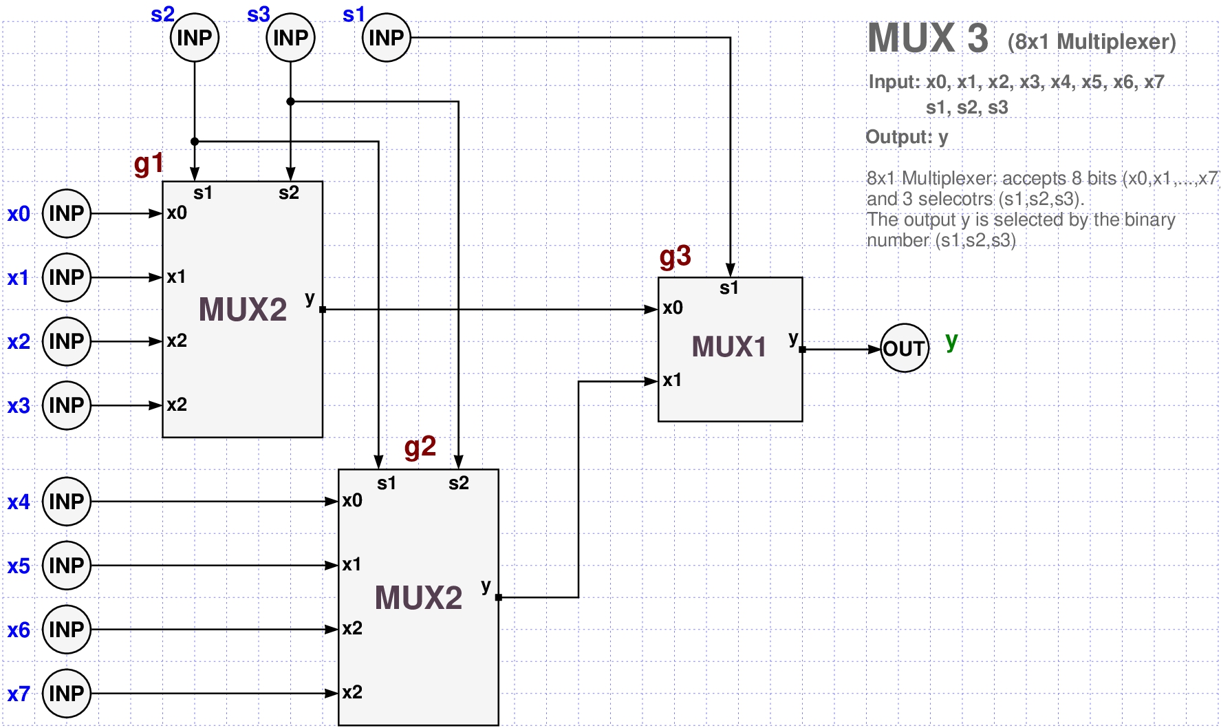
- As you can see from the diagram we now have 8 inputs bits:
x0, x1, x2, x3, x4, x5, x6, x7,
and one output bit: y. - We only need 3 logic gates: g1, g2, and g3.
- g1 and g2 are two instances of MUX2,
- g3 is an instance of MUX1.
- Here is the code for creating a PyCirc MUX3 object.
- Notice that this time we are using compressed notation technique for creating the 11 input gates in one line!
- The compressed notation can be used everywhere in PyCirc and saves a lot of typing!
need("mux2")

Define("mux3")
GATE("x<0:7>; s<1:3>", type="inp")
GATE("y", type="out")

GATE("g1", type="mux2")
GATE("g2", type="mux2")
GATE("g3", type="mux1")

WIRE("x0", "g1/x0")
WIRE("x1", "g1/x1")
WIRE("x2", "g1/x2")
WIRE("x3", "g1/x3")
WIRE("x4", "g2/x0")
WIRE("x5", "g2/x1")
WIRE("x6", "g2/x2")
WIRE("x7", "g2/x3")
WIRE("s2", "g1/s1")
WIRE("s2", "g2/s1")
WIRE("s3", "g1/s2")
WIRE("s3", "g2/s2")
WIRE("s1", "g3/s1")
WIRE("g1/y", "g3/x0")
WIRE("g2/y", "g3/x1")
WIRE("g3/y", "y")
EndDef()
Cell = mux3: Validity check: OK.
<pycirc.pycirc.PyCirc at 0x7f77136b5ad0>
mux3 = PyCirc["mux3"]

for g in mux3.gates:
    print(g)
gate id=81: name=x0, type=inp, value=(None), depth=0
gate id=82: name=x1, type=inp, value=(None), depth=0
gate id=83: name=x2, type=inp, value=(None), depth=0
gate id=84: name=x3, type=inp, value=(None), depth=0
gate id=85: name=x4, type=inp, value=(None), depth=0
gate id=86: name=x5, type=inp, value=(None), depth=0
gate id=87: name=x6, type=inp, value=(None), depth=0
gate id=88: name=x7, type=inp, value=(None), depth=0
gate id=89: name=s1, type=inp, value=(None), depth=0
gate id=90: name=s2, type=inp, value=(None), depth=0
gate id=91: name=s3, type=inp, value=(None), depth=0
gate id=92: name=y, type=out, value=(None), depth=3
gate id=93: name=g1, type=mux2, value=(y=None), depth=1
gate id=94: name=g2, type=mux2, value=(y=None), depth=1
gate id=95: name=g3, type=mux1, value=(y=None), depth=2
mux3 = PyCirc["mux3"]

for g in mux3.gates:
    print("%s = %s" % (g.name, g.get()))
x0 = None
x1 = None
x2 = None
x3 = None
x4 = None
x5 = None
x6 = None
x7 = None
s1 = None
s2 = None
s3 = None
y = None
g1 = y=None
g2 = y=None
g3 = y=None
for w in mux3.wires:
    print(w)
wire id=102:
  source=gate id=81: name=x0, type=inp, value=(None), depth=0
  target=gate id=93: name=g1, type=mux2, value=(y=None), depth=1
  source=None
  target=x0
wire id=103:
  source=gate id=82: name=x1, type=inp, value=(None), depth=0
  target=gate id=93: name=g1, type=mux2, value=(y=None), depth=1
  source=None
  target=x1
wire id=104:
  source=gate id=83: name=x2, type=inp, value=(None), depth=0
  target=gate id=93: name=g1, type=mux2, value=(y=None), depth=1
  source=None
  target=x2
wire id=105:
  source=gate id=84: name=x3, type=inp, value=(None), depth=0
  target=gate id=93: name=g1, type=mux2, value=(y=None), depth=1
  source=None
  target=x3
wire id=106:
  source=gate id=85: name=x4, type=inp, value=(None), depth=0
  target=gate id=94: name=g2, type=mux2, value=(y=None), depth=1
  source=None
  target=x0
wire id=107:
  source=gate id=86: name=x5, type=inp, value=(None), depth=0
  target=gate id=94: name=g2, type=mux2, value=(y=None), depth=1
  source=None
  target=x1
wire id=108:
  source=gate id=87: name=x6, type=inp, value=(None), depth=0
  target=gate id=94: name=g2, type=mux2, value=(y=None), depth=1
  source=None
  target=x2
wire id=109:
  source=gate id=88: name=x7, type=inp, value=(None), depth=0
  target=gate id=94: name=g2, type=mux2, value=(y=None), depth=1
  source=None
  target=x3
wire id=110:
  source=gate id=90: name=s2, type=inp, value=(None), depth=0
  target=gate id=93: name=g1, type=mux2, value=(y=None), depth=1
  source=None
  target=s1
wire id=111:
  source=gate id=90: name=s2, type=inp, value=(None), depth=0
  target=gate id=94: name=g2, type=mux2, value=(y=None), depth=1
  source=None
  target=s1
wire id=112:
  source=gate id=91: name=s3, type=inp, value=(None), depth=0
  target=gate id=93: name=g1, type=mux2, value=(y=None), depth=1
  source=None
  target=s2
wire id=113:
  source=gate id=91: name=s3, type=inp, value=(None), depth=0
  target=gate id=94: name=g2, type=mux2, value=(y=None), depth=1
  source=None
  target=s2
wire id=114:
  source=gate id=89: name=s1, type=inp, value=(None), depth=0
  target=gate id=95: name=g3, type=mux1, value=(y=None), depth=2
  source=None
  target=s1
wire id=115:
  source=gate id=93: name=g1, type=mux2, value=(y=None), depth=1
  target=gate id=95: name=g3, type=mux1, value=(y=None), depth=2
  source=y
  target=x0
wire id=116:
  source=gate id=94: name=g2, type=mux2, value=(y=None), depth=1
  target=gate id=95: name=g3, type=mux1, value=(y=None), depth=2
  source=y
  target=x1
wire id=117:
  source=gate id=95: name=g3, type=mux1, value=(y=None), depth=2
  target=gate id=92: name=y, type=out, value=(None), depth=3
  source=y
  target=None
- This is quite verbose and not too helpful except for debugging.
- We can extract a more focused output with code like this.
for w in mux3.wires:
    print("%s  =>  %s" % (w.source, w.target))
x0  =>  g1/x0
x1  =>  g1/x1
x2  =>  g1/x2
x3  =>  g1/x3
x4  =>  g2/x0
x5  =>  g2/x1
x6  =>  g2/x2
x7  =>  g2/x3
s2  =>  g1/s1
s2  =>  g2/s1
s3  =>  g1/s2
s3  =>  g2/s2
s1  =>  g3/s1
g1/y  =>  g3/x0
g2/y  =>  g3/x1
g3/y  =>  y
a = Assign("x<0:7> ; s<1:3>", "00001000" + "000")
mux3.set(a)
for x in mux3.input:
    print("%s = %d" % (x.name, x.value))

g3 = mux3["g3"]

for g in mux3.in_gates(g3):
    print(g)
print("Depth =", mux3.depth)
x0 = 0
x1 = 0
x2 = 0
x3 = 0
x4 = 1
x5 = 0
x6 = 0
x7 = 0
s1 = 0
s2 = 0
s3 = 0
gate id=89: name=s1, type=inp, value=(0), depth=0
gate id=93: name=g1, type=mux2, value=(y=None), depth=1
gate id=94: name=g2, type=mux2, value=(y=None), depth=1
Depth = 3
a = Assign("x<0:7> ; s<1:3>", "00000011" + "111")
print("Input:")
print(a)
o = mux3(a)
print("Output:")
print(o)
Input:
x0=0, x1=0, x2=0, x3=0, x4=0, x5=0, x6=1, x7=1, s1=1, s2=1, s3=1
Output:
y=1
3-bits Adder Design
Here is a simple design for 3 bits adder with carry in (cin) and carry out (cout) bits

- This circuit acceps three types of input
- two binary numbers: $(a_2,a_1,a_0)$, $(b_2,b_1,b_0)$
- a carry in bit:
cin.
- Its output $(y_2,y_1,y_0)$ is the binary sum of the two numbers (with the carry added).
- In case of addition overflow, we need a carry out (cout) output bit as well.
- The following PyCirc code is the PyCirc model for the ADDER3 cell.
# ADDER3
# Input:  a2, a1, a0, b2, b1, b0, cin
# Output: y2, y1, y0, cout

Define("adder3")
GATE("a2", type="inp")
GATE("a1", type="inp")
GATE("a0", type="inp")

GATE("b2", type="inp")
GATE("b1", type="inp")
GATE("b0", type="inp")

GATE("cin", type="inp")

GATE("y2", type="out")
GATE("y1", type="out")
GATE("y0", type="out")

GATE("cout", type="out")

GATE("g1", type="xor2")
GATE("g2", type="xor2")
GATE("g3", type="xor2")
GATE("g4", type="mux1")
GATE("g5", type="mux1")
GATE("g6", type="mux1")
GATE("g7", type="xor2")
GATE("g8", type="xor2")
GATE("g9", type="xor2")

WIRE("a2", "g3/x2")
WIRE("a2", "g6/x0")
WIRE("a1", "g2/x2")
WIRE("a0", "g1/x2")
WIRE("a0", "g4/x0")
WIRE("b2", "g3/x1")
WIRE("b1", "g2/x1")
WIRE("b1", "g5/x0")
WIRE("b0", "g4/x1")
WIRE("b0", "g9/x2")
WIRE("cin", "g1/x1")
WIRE("g1/y", "g4/s1")
WIRE("g1/y", "g9/x1")
WIRE("g2/y", "g5/s1")
WIRE("g2/y", "g8/x2")
WIRE("g3/y", "g6/s1")
WIRE("g3/y", "g7/x2")
WIRE("g4/y", "g5/x1")
WIRE("g4/y", "g8/x1")
WIRE("g5/y", "g6/x1")
WIRE("g5/y", "g7/x1")
WIRE("g6/y", "cout")
WIRE("g7/y", "y2")
WIRE("g8/y", "y1")
WIRE("g9/y", "y0")
EndDef()
Cell = adder3: Validity check: OK.
<pycirc.pycirc.PyCirc at 0x7f7713678710>
- This is the compressed version of this code.
- The number of lines was reduced by half! (from 46 to 23).
# ADDER3, compressed version
# Input:  a2, a1, a0, b2, b1, b0, cin
# Output: y2, y1, y0, cout

Define("adder3")
GATE("a<2:0>", type="inp")
GATE("b<2:0>", type="inp")
GATE("cin", type="inp")
GATE("y<2:0>", type="out")
GATE("cout", type="out")

GATE("g<1:3,7:9>", type="xor2")
GATE("g<4:6>", type="mux1")

WIRE("a2", "g3/x2; g6/x0")
WIRE("a1", "g2/x2")
WIRE("a0", "g1/x2; g4/x0")
WIRE("b2", "g3/x1")
WIRE("b1", "g2/x1; g5/x0")
WIRE("b0", "g4/x1; g9/x2")
WIRE("cin", "g1/x1")
WIRE("g1/y", "g4/s1; g9/x1")
WIRE("g2/y", "g5/s1; g8/x2")
WIRE("g3/y", "g6/s1; g7/x2")
WIRE("g4/y", "g5/x1; g8/x1")
WIRE("g5/y", "g6/x1; g7/x1")
WIRE("g6/y", "cout")
WIRE("g<7:9>/y", "y<2:0>")
EndDef()
Cell = adder3: Validity check: OK.
<pycirc.pycirc.PyCirc at 0x7f7713b1dfd0>
adder3 = PyCirc["adder3"]
- Lets test our adder by verifying that
011+011=110
bits = "011" + "011" + "0"
a = Assign("a<2:0>; b<2:0>; cin", bits)
o = adder3(a)
cin = a["cin"]
cout = o["cout"]
A = a.bits("a<2:0>")
B = a.bits("b<2:0>")
Y = o.bits("y<2:0>")
print("%s + %s = %s : cin=%s cout=%s" % (A,B,Y,cin,cout))
011 + 011 = 110 : cin=0 cout=0
ADDER9 - 9-bits Adder Design
- Here is a simple PyCirc Design Diagram for the standard 9-bits adder with a carry in (cin) and carry out (cout) bits.
- It uses 3 gates g1, g2, g3, of type ADDER3 which are chained by their cout/cin pins.
- Input:
a<8:0> + b<8:0> + cin Output:
y<8:0> + cout
- Here is a compressed PyCirc code for ADDER9:
# ADDER9
# Input:  a8, a7, a6, a5, a4, a3, a2, a1, a0, b8, b7, b6, b5, b4, b3, b2, b1, b0, cin
# Output: y8, y7, y6, y5, y4, y3, y2, y1, y0, cout

need("adder3")

Define("adder9")
GATE("a<8:0>;b<8:0>", type="inp")
GATE("cin", type="inp")
GATE("y<8:0>", type="out")
GATE("cout", type="out")
GATE("g1", type="adder3")              # First ADDER3 gate
GATE("g2", type="adder3")              # Second ADDER3 gate
GATE("g3", type="adder3")              # Third ADDER3 gate

WIRE("a<0:2>", "g1/a<0:2>"),
WIRE("a<3:5>", "g2/a<0:2>"),
WIRE("a<6:8>", "g3/a<0:2>"),
WIRE("b<0:2>", "g1/b<0:2>"),
WIRE("b<3:5>", "g2/b<0:2>"),
WIRE("b<6:8>", "g3/b<0:2>"),
WIRE("cin", "g1/cin"),
WIRE("g1/cout", "g2/cin"),
WIRE("g2/cout", "g3/cin"),
WIRE("g3/cout", "cout"),
WIRE("g1/y<0:2>", "y<0:2>"),
WIRE("g2/y<0:2>", "y<3:5>"),
WIRE("g3/y<0:2>", "y<6:8>"),
EndDef()
Cell = adder9: Validity check: OK.
<pycirc.pycirc.PyCirc at 0x7f77172bead0>
- The
full_runutility can be used for traversing all input/output pairs. - Interactively.
- To stop: press "q".
adder9 = PyCirc["adder9"]

full_run(adder9)
Input:
a8=0, a7=0, a6=0, a5=0, a4=0, a3=0, a2=0, a1=0, a0=0, b8=0, b7=0, b6=0, b5=0, b4=0, b3=0, b2=0, b1=0, b0=0, cin=0
Output:
y8=0, y7=0, y6=0, y5=0, y4=0, y3=0, y2=0, y1=0, y0=0, cout=0
Press <Enter> to continue or 'q' to quit
Next?
Input:
a8=0, a7=0, a6=0, a5=0, a4=0, a3=0, a2=0, a1=0, a0=0, b8=0, b7=0, b6=0, b5=0, b4=0, b3=0, b2=0, b1=0, b0=0, cin=1
Output:
y8=0, y7=0, y6=0, y5=0, y4=0, y3=0, y2=0, y1=0, y0=1, cout=0
Press <Enter> to continue or 'q' to quit
Next?
Input:
a8=0, a7=0, a6=0, a5=0, a4=0, a3=0, a2=0, a1=0, a0=0, b8=0, b7=0, b6=0, b5=0, b4=0, b3=0, b2=0, b1=0, b0=1, cin=0
Output:
y8=0, y7=0, y6=0, y5=0, y4=0, y3=0, y2=0, y1=0, y0=1, cout=0
Press <Enter> to continue or 'q' to quit
Next? q
- However this is not readable and takes forever!
- Number of inputs is 17 bits, so the loop has $2^{17} = 131072$ cycles!
- We will better off running only random assignments, and verify them manually.
- The pycirc package has the following utility for creating a random assignment.
def random_assignment(names):
  names = expand(names)
  a = Assign(names)
  for x in names:
      a[x] = randint(0,1)
  return a
- Here are 5 random samples on our ADDER3 input
names = "a<8:0>; b<8:0>; cin"
for i in range(5):
    a = random_assignment(names)
    A = a.bits("a<8:0>")
    B = a.bits("b<8:0>")
    print(A, B, a["cin"])
111100010 001000100 1
100010101 101000011 0
000011000 001011101 1
111001111 000111101 1
100100010 111110100 0
- Now we can generate random inputs for ADDER9, get the output, and verify its correctness.
names = "a<8:0>; b<8:0>; cin"
while True:
    a = random_assignment(names)
    A = a.bits("a<8:0>")
    B = a.bits("b<8:0>")
    cin = a["cin"]
    print(80*"-")
    print("Input: %s + %s + %s" % (A, B, cin))
    o = adder9(a)
    Y = o.bits("y<8:0>")
    cout = o["cout"]
    print("Output: %s + %s" % (Y, cout))
    print("Verify sum: %s" % (bin(int(A,2) + int(B,2)),))
    inpstr = input("Press <Enter> to continue or q to stop: ")
    if "q" == inpstr:
        break
--------------------------------------------------------------------------------
Input: 101010110 + 011101101 + 0
Output: 001000011 + 1
Verify sum: 0b1001000011
Press <Enter> to continue or q to stop:
--------------------------------------------------------------------------------
Input: 111001010 + 110111110 + 0
Output: 110001000 + 1
Verify sum: 0b1110001000
Press <Enter> to continue or q to stop:
--------------------------------------------------------------------------------
Input: 011011001 + 110001101 + 1
Output: 001100111 + 1
Verify sum: 0b1001100110
Press <Enter> to continue or q to stop: q
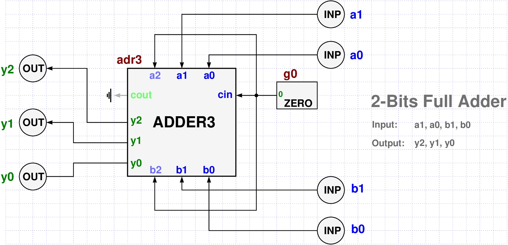
Full Adder
- A full adder is a the same thing except that it does not have carry bits.
- It simply adds its two input bits and outputs the sum.
- In general, an n-bits full adder has $2n$ inputs bits "a0:n-1" + "b<0:n-1" and $n+1$ output bits "y0:n".
- We will use our ADDER3 cell to build a full 2-bits adder
- by injecting a zero constant to its cin input,
- and discarding its cout output bit.
- We will also use this opportunity to present a different style for creating a PyCirc cell.
# CELL: FULL ADDER 2

# We need adder3
need("adder3")

# Here we present a different style for defining a logic circuit

gates = (
  GATE("a1", type="inp")
+ GATE("a0", type="inp")
+ GATE("b1", type="inp")
+ GATE("b0", type="inp")
+ GATE("ad3", type="adder3")
+ GATE("y2", type="out")
+ GATE("y1", type="out")
+ GATE("y0", type="out")
+ GATE("g0", type="zero")
)

wires = [
    Wire("a0", "ad3/a0"),
    Wire("a1", "ad3/a1"),
    Wire("b0", "ad3/b0"),
    Wire("b1", "ad3/b1"),
    Wire("g0", "ad3/a2"),
    Wire("g0", "ad3/b2"),
    Wire("g0", "ad3/cin"),
    Wire("ad3/y0", "y0"),
    Wire("ad3/y1", "y1"),
    Wire("ad3/y2", "y2"),
]

fa2 = PyCirc("full_adder2", gates, wires)
pycircLib.add_circ(fa2)
ATTENTION: some outputs are dangling! ad3 (adder3) : {'cout'}
Cell = full_adder2: Validity check: OK.
<pycirc.pycirc.Cell at 0x7f77172beb90>
- Notice that in this case, we do not have a Define(), EndDef() calls!
- We simply define a list of gates and a list of wires, and later use the class PyCirc to create the cell.
- The wires are created by the low level
Wireclass instead of the higher levelWIREfunction.- The
Wireclass is suited for generating a single wire object whileWIEREgenerates multiple wires and supports compressed names.
- The
- An output pin which is not connected to any other pin is called a dangling pin.
- Notice that our 2-bits full adder FA2 has a dangling pin.
- The carry out bit (cout) of the gate ad3 is dangling.
- Also notice the constant gate
g0which fixes the carry in (cin) to a constant 0 value. A "dangling output" allert means that an output is not connected to anything.
- This is OK if you intended it as we did in this example.
- To achieve a full adder we had to discard the
coutpin of ADDER3.
Boolean Operators
- The PyCirc package contains a logops module which defines a small set of boolean functions.
- These functions are also called boolean operators since
- they act on a variable number of boolean values.
- return a boolean value.
- These operators are needed for designing black box cells that play an important role in the VLSI design process.
- Here are a few examples of operators we have
in the pycirc package:
- AND, OR, NOR, XOR, NOT, MUX.
- They all accept an Assign object as an argument,
- and return an Assign object.
def AND(a, output="y"):
    o = Assign(output)
    for x in a:
        if a[x] == 0:
            for y in o: o[y] = 0
            return o
    for y in o: o[y] = 1
    return o

def OR(a, output="y"):
    o = Assign(output)
    for x in a:
        if a[x] == 1:
            for y in o: o[y] = 1
            return o
    for y in o: o[y] = 0
    return o

def NOR(a, output="y"):
    o = Assign(output)
    o1 = OR(a, Assign("y"))
    b = Assign("x", o1["y"])
    return NOT(b, o)

def XOR(a, output="y"):
    o = Assign(output)
    if sum(a[x] for x in a) == 1:
        for y in o: o[y] = 1
        return o
    else:
        for y in o: o[y] = 0
        return o
- Users can easily add more operators in client code.
- Here are two examples that we used in the development of pycirc for testing the various 1-bit counter cells and the magnitude comparator cells.
- The first operator is simply a Python code for counting how many
1-bits a given assigmnet object
ahas?
# Count the number of 1-bits in the assignment a
def COUNT_ONES(a):
    s = sum(a())
    k = len(a).bit_length()
    bits = bin(s)[2:].zfill(k)
    names = "y<%d:1>" % (k,)
    bits = [int(y) for y in bits]
    o = Assign(names, bits)
    return o

# Magnitude Comparator Operator
# input: "a<0:n>;b<0:n>"
# output: "y<1:3>"
# If a<b returns 100
# If a==b returns 010
# If a>b returns 001
def COMPARE(a):
    A = []
    B = []
    for name in a:
        if name[0] == "a":
            A.append(name)
        else:
            B.append(name)
    A = int(a.bits(A), 2)
    B = int(a.bits(B), 2)
    o = Assign("y<1:3>")
    if A<B:
        o.assign("100")
    elif A==B:
        o.assign("010")
    else:
        o.assign("001")
    return o
a = Assign("x<1:5>", "01011")
o = COUNT_ONES(a)
print(o)
y3=0, y2=1, y1=1
- Note that the result is in numerical binary form: 011.
- The input "01011" has 3 occurrences of the bit 1, which in numerical binary form is 11.
a = Assign("x<1:8>", "11101011")
print("Input:", a.bits())
o = COUNT_ONES(a)
print("Output (binary):", o.bits())
print("Output (decimal):", int(o.bits(), 2))
Input: 11101011
Output (binary): 0110
Output (decimal): 6
- Here, the input "11101011" contains 6 bits of 1.
- As expected, the output is 110 which is a numerical binary representation of decimal 6.
- The following operators do not accept any input but produces a constant output.
- These are the constant operators.
- The ZERO operator produces 0.
- The ONE operator produces 1.
- Here are the definitions of the ZERO and ONE operators
def ZERO(a=None, output="y"):
    o = Assign(output)
    for y in o: o[y] = 0
    return o

def ONE(a=None, output="y"):
    o = Assign(output)
    for y in o: o[y] = 1
    return o
- The Magnitude Comparator operator acts on even length assignments only.
- It splits the input to two equal length binary numbers and compares their magnitude.
a = Assign("a<0:7>; b<0:7>", "00101101" + "00110101")
o = COMPARE(a)
print(o)
y1=1, y2=0, y3=0
Creating Cells with the Cell Class
- VLSI design usually means designing very large logic circuits consisting of millions and even billions of elements.
- This is achieved by dividing the main circuit to a dozen or so sub-circuits, usually called sections.
- Each section is divided to a set of smaller cells, usually called blocks.
- Each block is partitioned to smaller cells, usually called functional unit blocks (or fubs for short).
- And finally, each functional unit is partitioned to smaller cells taken from established cell libraries.
- This design method is usually called Hierarchical Design.
For example, here is a high level hierarchical view of Intel's Skylake cpu

- It consists of roughly 5 billion transistors and 20 billion wires.
- In the early design phase, only a small number of the cell designs are available.
- Many other cells are replaced by "black boxes" that simulate cells, but their full circuit design is postponed to a later stage after passing many fire tests that verify the feasibility of the overall design.
- These simulation tests determine many of the desired properties and parameters for these cells, and thus provide a lot of information and clues needed to design them efficiently.
- In such scenarios, a Logic Cell is viewed as a "black box" with entry and exit points that can be defined more conveniently by means of simple numerical software algorithms.
- PyCirc provides a high level Cell class for defining such cells.
- So we have two ways to define a new cell:
- By defining a PyCirc circuit as in the examples above
- By defining a boolean operator numerically.
- A cell defined by an operator is named black box or box for short.
- It is a place holder for a real circuit which is not yet available, but the overall design need to be tested before it is decided if its design is feasible.
- Here is an example of a 4x3 cell that is defined by
the
Cellclass.
count3 = Cell("count3", operator=COUNT_ONES, input="x<1:3>", output="y<1:2>", depth=3)
# currently all box type Cells are stored in the default PyCirc library called pycircLib
pycircLib.add(count3)
- It accepts a 4-bits assignment and outputs a 3-bits assignment.
- It counts the number of 1-bits in the input.
- The operator COUNT_ONES was defined in the section above.
- We can now use count3 as a cell type and use it to define more complex cells.
As an example, let's define a COUNT6 circuit by using two gates of type COUNT3.

- The plan is straightforward:
- COUNT6 accepts 6 input bits: x1, x2, x3, x4, x5, x6.
- The first 3 bits x1, x2, x3, are assigned to the gate c1 whose type is COUNT3.
- The last 3 bits x4, x5, x6, are assigned to the gate c2 whose type is also COUNT3.
- The outputs of c1 and c2 are sent to gate a which is a FULL_ADDER2.
- The gate a is adding up the two numbers and sends its output to y1, y2, y3.
- Here is the PyCirc Program for the COUNT6 circuit.
Define("count6")
GATE("x<1:6>", type="inp")
GATE("y<1:3>", type="out")
GATE("c1", type="count3")            # Gate "c1" of type count3
GATE("c2", type="count3")            # Gate "c2" of type count3
GATE("a", type="full_adder2")

WIRE("x<1:3>", "c1/x<1:3>")
WIRE("x<4:6>", "c2/x<1:3>")
WIRE("c1/y1", "a/a1")
WIRE("c1/y2", "a/a0")
WIRE("c2/y1", "a/b1")
WIRE("c2/y2", "a/b0")
WIRE("a/y<2:0>", "y<1:3>")
EndDef()
Cell = count6: Validity check: OK.
<pycirc.pycirc.PyCirc at 0x7f7713661bd0>
- Here is the Python code for adding some of the box cells in PyCirc.
See the factory module in the PyCirc package for more examples.
pycircLib.add_box(name="and2", operator=AND,  input="x<1:2>", output=["y"])
pycircLib.add_box(name="and3", operator=AND,  input="x<1:3>", output=["y"])
pycircLib.add_box(name="and4", operator=AND,  input="x<1:4>", output=["y"])
pycircLib.add_box(name="and5", operator=AND,  input="x<1:5>", output=["y"])
pycircLib.add_box(name="and6", operator=AND,  input="x<1:6>", output=["y"])
pycircLib.add_box(name="and7", operator=AND,  input="x<1:7>", output=["y"])
pycircLib.add_box(name="and8", operator=AND,  input="x<1:8>", output=["y"])
We can also use Python loops to add box cells to our cell library.
The following Python loop, adds 32 box cellls to the PyCirc cell library
- 8 OR box cells: OR2, OR3, ..., OR8
- 8 XOR box cells: XOR2, XOR3, ..., XOR8
- 8 NOR box cells: NOR2, NOR3, ..., NOR8
for k in range(2,9):
  inp = "x<1:%s>" % (k,)
  name = "or" + str(k)
  pycircLib.add_box(name, operator=OR, input=inp, output=["y"])
  name = "xor" + str(k)
  pycircLib.add_box(name, operator=XOR, input=inp, output=["y"])
  name = "nor" + str(k)
  pycircLib.add_box(name, operator=NOR, input=inp, output=["y"])
  name = "nand" + str(k)
  pycircLib.add_box(name, operator=NAND, input=inp, output=["y"])
Advanced Topics -- To be Continued ...
- For the more experienced students we present here some more advanced usage of the PyCirc package will be added within the near future. To be contniued ...
from IPython.display import HTML
from urllib.request import urlopen
css = urlopen("https://samyzaf.com/css/pycirc.css").read().decode('utf-8')
HTML('<style>{}</style>'.format(css))